Raspberry Pi

Enabling 433Utils on the Rasberry Pi

First install wiringPI to access the GPIO headers on the PI.


git clone git://git.drogon.net/wiringPi && cd wiringPi &&./build

Confirm the wiringPI library is working by listing the GPIO pin allocation:

gpio -v
gpio readall

Should display something like:

 +-----+-----+---------+------+---+---Pi 3---+---+------+---------+-----+-----+
 | BCM | wPi |   Name  | Mode | V | Physical | V | Mode | Name    | wPi | BCM |
 +-----+-----+---------+------+---+----++----+---+------+---------+-----+-----+
 |     |     |    3.3v |      |   |  1 || 2  |   |      | 5v      |     |     |
 |   2 |   8 |   SDA.1 |   IN | 1 |  3 || 4  |   |      | 5v      |     |     |
 |   3 |   9 |   SCL.1 |   IN | 1 |  5 || 6  |   |      | 0v      |     |     |
 |   4 |   7 | GPIO. 7 |   IN | 1 |  7 || 8  | 0 | IN   | TxD     | 15  | 14  |
 |     |     |      0v |      |   |  9 || 10 | 1 | IN   | RxD     | 16  | 15  |
 |  17 |   0 | GPIO. 0 |   IN | 0 | 11 || 12 | 0 | IN   | GPIO. 1 | 1   | 18  |
 |  27 |   2 | GPIO. 2 |   IN | 0 | 13 || 14 |   |      | 0v      |     |     |
 |  22 |   3 | GPIO. 3 |   IN | 0 | 15 || 16 | 0 | IN   | GPIO. 4 | 4   | 23  |
 |     |     |    3.3v |      |   | 17 || 18 | 0 | IN   | GPIO. 5 | 5   | 24  |
 |  10 |  12 |    MOSI |   IN | 0 | 19 || 20 |   |      | 0v      |     |     |
 |   9 |  13 |    MISO |   IN | 0 | 21 || 22 | 0 | IN   | GPIO. 6 | 6   | 25  |
 |  11 |  14 |    SCLK |   IN | 0 | 23 || 24 | 1 | IN   | CE0     | 10  | 8   |
 |     |     |      0v |      |   | 25 || 26 | 1 | IN   | CE1     | 11  | 7   |
 |   0 |  30 |   SDA.0 |   IN | 1 | 27 || 28 | 1 | IN   | SCL.0   | 31  | 1   |
 |   5 |  21 | GPIO.21 |   IN | 1 | 29 || 30 |   |      | 0v      |     |     |
 |   6 |  22 | GPIO.22 |   IN | 1 | 31 || 32 | 0 | IN   | GPIO.26 | 26  | 12  |
 |  13 |  23 | GPIO.23 |   IN | 0 | 33 || 34 |   |      | 0v      |     |     |
 |  19 |  24 | GPIO.24 |   IN | 0 | 35 || 36 | 0 | IN   | GPIO.27 | 27  | 16  |
 |  26 |  25 | GPIO.25 |   IN | 0 | 37 || 38 | 0 | IN   | GPIO.28 | 28  | 20  |
 |     |     |      0v |      |   | 39 || 40 | 0 | IN   | GPIO.29 | 29  | 21  |
 +-----+-----+---------+------+---+----++----+---+------+---------+-----+-----+
 | BCM | wPi |   Name  | Mode | V | Physical | V | Mode | Name    | wPi | BCM |
 +-----+-----+---------+------+---+---Pi 3---+---+------+---------+-----+-----+

Next install the 433Util package:

git clone https://github.com/rotv/433Utils.git
cd 433Utils
git submodule init
git submodule update
cd RPi_utils
make
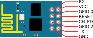
Connect and Program an ESP8266 With a Raspberry Pi

This small tutorial is meant to help you connect the ESP8266 wifi module to Raspberry Pi through the serial port. It will show you how to run a simple AT command and how to connect the chip to your wireless router using these commands.

Before starting the wiring, I highly recommend you to use a breadboard.

You can use the following table as a wiring guide.
Ex: VCC and CH_PD from Wifi module are connected to Pin 1 from Raspberry.

ESP8266 Raspberry Pi B
VCC and CH_PD Pin 1 (3V3)
GND Pin 9 (Ground)
TX Pin 10 (GPIO 15)
RX Pin 8 (GPIO 14)
esp8266_pinout_h-569x236 pinout2

After you finish the wiring you can plug in the power into Raspberry.

Now we’ve reached to the phase where we want to access the ESP8266 module through serial port. For this we need a tool called minicom, but first we need to disable Serial Port Login and some Bootup info on Raspberry. You can do that by following the next short steps

Disable serial port login:
Open /etc/inittab and search for the following line:

T0:23:respawn:/sbin/getty -L ttyAMA0 115200 vt100

You need to comment this line by adding # at the beginning of the line.

#T0:23:respawn:/sbin/getty -L ttyAMA0 115200 vt100

Disable bootup info:

This part is optional. At every boot Raspberry will send all bootup information through serial port. If you want to keep that information to be sent, just skip this step.
Remove all ttyAMA0 references from /boot/cmdline.txt

dwc_otg.lpm_enable=0 console=ttyAMA0,115200 kgdboc=ttyAMA0,115200 console=tty1 root=/dev/mmcblk0p2 rootfstype=ext4 elevator=deadline rootwait

After deletion, it should look like the following code:

dwc_otg.lpm_enable=0 console=tty1 root=/dev/mmcblk0p2 rootfstype=ext4 elevator=deadline rootwait

Now we must reboot the Raspberry!

sudo shutdown -r now

The next step is to install minicom and connect to the wifi module. It will help us to communicate with the ESP8266 by offering us an interface where we can run the AT commands.

# Install minicon
sudo apt-get install minicom

# Connect to wifi module
minicom -b 115200 -o -D /dev/ttyAMA0

If everything went well you should see the minicom serial interface. Try to write AT+RST and hit Enter. If it will print some info it means that you are ready to go.

Connect to your home router

AT+CWJAP="dlink","password"

Where dlink is your router name (SSID) and password is the router password.

Configure Network Settings on Raspberry Pi Hardware

You can resolve network connectivity issues by inspecting and editing the IP configuration of the Raspberry Pi™ Ethernet port.

You may need to reconfigure the IP settings if your board:

  • Has unknown IP settings

  • Is unreachable using a network connection

  • Is being moved to a network or direct Ethernet connection that uses static IP settings

  • Is being moved from a network that used static IP settings to one that uses DHCP services

There are several conditions under which networks use DHCP or static IP settings:

  • Use DHCP services — If your board is connected to a network with DHCP services, such as an office LAN or a home network connected to the Internet. DHCP is a network service that automatically configures the IP settings of Ethernet devices connected to a network.

  • Use static IP settings — If your board is directly connected to an Ethernet port on your computer or connected to an isolated network without DHCP services.

To configure the board to use DHCP or static IP settings:

  1. You can use a terminal window after accessing the Linux desktop.

  2. Display the contents of the /etc/network/interfaces file.
    Enter:

    cat /etc/network/interfaces

    If the board is configured to use DHCP services (the default configuration), dhcp appears at the end of the following line:

    iface eth0 inet dhcp

    If the board is configured to use static IP settings, static appears at the end of the following line:

    iface eth0 inet static

  3. Create a backup of the /etc/network/interfaces file.
    Enter:

    sudo cp /etc/network/interfaces /etc/network/interfaces.backup

    If prompted, enter the root password.

  4. Edit interfaces using a simple editor called nano. Enter:sudo nano /etc/network/interfaces

  5. Edit the last word of line that starts with iface eth0 inet.

    To use DHCP services, change the line to:

    iface eth0 inet dhcp

    To use static IP settings, change the line to:

    iface eth0 inet static

  6. For static IP settings, add lines for address, netmask,
    and gateway. For example:

    iface eth0 inet static
    address 192.168.1.2
    netmask 255.255.255.0
    gateway 192.168.1.1

    For static IP settings:

    • The value of the subnet mask must be the same for
      all devices on the network.

    • The value of the IP address must be unique for each device on the network.

    For example, if the Ethernet port on your host computer has a network mask of 255.255.255.0 and a static IP address of 192.168.1.1, set:

    • netmask to use the same network mask value, 255.255.255.0.

    • address to an unused IP address,
      between 192.168.1.2 and 192.168.1.254.

  7. Save the changes and exit nano:

    1. Press Ctrl+X.

    2. Enter Y to save the modified buffer.

    3. For “File Name to Write: /etc/network/interfaces”,
      press Enter.

    4. The nano editor confirms that it
      “Wrote # lines” and returns control to the command line.

  8. Reboot the board. In MATLAB Command Window, enter:

    h = raspberrypi h.execute(‘sudo shutdown -r now’)

  9. Test the IP settings by logging in to the board over a telnet session.